< Installing the Chrysler Electronic Voice Alert

Installing the Chrysler Electronic Voice Alert

24 Function Unit

or

"How to have a meaningful conversation with your car"


I wanted another interesting toy in my car, but as usual, I did not want to spent much money.  I had an EVA in my 84 Laser and I missed it. I named the EVA in the Laser "Mortimer". The EVA was inexpensive, ($10 worth of junkyard parts) but it took a good bit of work. This page details the ongoing project of installing EVA units in my Daytonas.  I have finished installing the EVA in my 88 Daytona! It works great. When my wife first heard the EVA work in my 88 Daytona, she exclaimed "Mortimer's back!"

I did not install the brake pad wear wire, but I may still hook it up. The special brake pads with the wear sensors cost $86!! I think I can easily make and install my own wear sensors. I'm looking for some original EVA brake pads so I can determine how I need to make my owh sensors.  I'm still trying to find French and Spanish speaking 24 function EVA units.

Caution: You must be able to work with your cars' electrical system competently to perform this job.  Mis-wiring can cause damage to electrical components and fire hazards.  The instructions and wiring diagrams may not be correct or applicable to your car, so use this information at your own risk.  I have installed this unit successfully in my car, but I found quite a few minor errors in the Factory wiring diagrams. You must know what you are doing or you will ruin your car trying to install the EVA!

Tools and materials

Parts needed for EVA installation

Identifying wires on EVA plugs

Identifying wires on car

Initial installation

Installing additional wires and sensors


Tools and materials

Factory Service Manual and wiring diagrams for vehicle (not the Haynes or Chilton manuals)

Factory Service Manual for donor car (optional, but recommended)

Soldering gun and solder

Heat shrink tubing, friction tape (good quality electric tape will work)

Miscellaneous screwdrivers and wrenches

Tie wraps

Stranded copper wire - use gauges specified in wiring diagrams -  from donor car

12 large boxes of Cheese Nips or equivalent

4 gallons ice tea or beverage of choice

Parts needed for EVA installation

Speech synthesis unit and mounting brackets

Electronic monitor

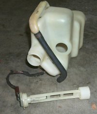
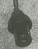
Radiator overflow tank with level sensor

Brake fluid level sensor

Rear washer fluid tank with level sensor (if needed)

Transmission pressure sensor (auto only)

Temperature switch (analog instruments only)

Rear lamp outage sensor

Headlamp outage sensor

Plugs and as much wiring as possible for all the above -
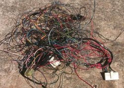
the EVA units are useless without the plugs!

I removed the wiring harness between the Electronic Monitor and the Speech synthesis module on the donor car. I had some difficulty cutting through the large bundles of wires.

Identifying wires on EVA plugs

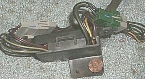
Before labeling the wires, I removed all the tape from the pieces of wiring harness so I could remove the unnecessary wire.  At this point, the wires looked like a hopeless jumbled mess! 

Is it al dente yet?


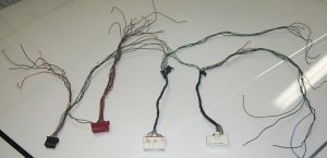
I had many wires and four plugs - two for the Electronic Monitor and two for the Speech Module.  Using the diagrams on the Speech Synthesis Module page and the Electronic Monitor page I labeled each wire on the four plugs.  Some of the wire colors had faded a little, making identification difficult.  I double checked the wire color against the plug cavity number.

Nice neat wires


Identifying wires on car

Two plugs on the dashboard wiring harness need modification or replacement for EVA installation - The standard message center plug and the chimes plug.  On some cars, the chimes plug is the same as one of the speech module plugs, but it is wired differently.  Do not attach this plug to the EVA unit without checking and modifying the wiring!  On my 87 and 88 Daytonas, I cut off the standard message center and chimes plugs, and spliced the wires  into the EVA plugs. I wanted to install a plug on the EVA harness to mate with the existing plugs, but I could not find the parts. The diagrams here cover the 1987 and 1988 Daytona wiring. The factory shop manual is a must to identify the wires on the car.


Chimes Plug on Non-EVA cars  1987,1988

Cavity Color Function Connect to
 1  DB* +12 V ignition switch  sp module plug 2 pin 30
 2  LG  seat belt switch sp module plug 2 pin 29
 3  LG/TN* shoulder belt switch ***1987 and 1988 only
 4  RD +12V battery  Not needed for EVA ****
 5  BK/LB ground sp module plug 2 pin 33
 6  DB/RD*  seat belt indicator sp module plug 2 pin 32
 7  LB  Key in switch sp module plug 2 pin 26

  *** Connect this wire to speech synthesis module plug 2 pin 25 ONLY if the donor module is from an 1987 J body car.

**** +12v from battery, supplies power to glove box light and chimes.  Connect to glove box light when installing EVA.


Standard Message Center Plug - Non EVA cars 

1987,1988 possibly other years, wire color is probably the same for most cars.  

Cut all these wires off the plug and connect to the Electronic Monitor plug.

Cavity Color Function Connect to
 A  TN Left door ajar switch   Emon plug 1 pin 18 
 B  - not used   
 C  BK/TN* Panel ground  emon plug 2 pin 28
 D  OR Illumination  Emon plug 1 pin 3
 E  BK/TN* Washer fluid low sensor  Emon plug 1 pin 2
 F  TN/RD*  Right door ajar switch Emon plug 1 pin 21
 G  DB* +12V from ignition switch  Emon plug 2 pin 22
 H  - not used   
 J  - not used   
 K  LB* low fuel sensor  emon plug 1 pin 6
 L TN/BK* Rear hatch ajar switch  emon plug 1 pin 16


Initial Installation

The initial installation consists of hooking up all the wires from the chimes plug and standard message center plug. Additional wires needed in this step and connection points are listed below.

Wire Connection Point Color
Time Delay Relay Lower steering column YL/RD*
Engine temperature signal Digital cluster or add temp switch  
Low oil pressure sensor Gage cluster GY
Headlight switch*** Headlight switch plug LB on switch BR on EVA
Parking Brake switch Run new wire from switch BK*
Speed sensor Navigator harness  
Engine speed Gage Cluster  
Display dimming Navigator harness  

*** In non EVA cars, the headlight on and seatbelt chimes both use the light blue wire.  When installing the EVA, I disconnected the light blue wire from the headlight switch so that only the key in switch used the wire.  I connected a wire from the headlight switch (where the light blue wire was connected) to the electronic monitor plug.


At this point in the installation, I powered up the EVA unit to make sure everything worked properly.  Fortunately, the EVA and everything else works!


Installing Additional Sensors


Engine Temperature

If the car has digital instruments, the digital cluster sends a ground signal to the Electronic Monitor when the temperature signal reaches a certain level. If the car has analog instruments (as my cars do) then a temperture switch must be installed on the engine to give the Electronic Monitor a high temperature signal. I purchased a temperature switch as used on 2.2 and 2.5 engines that do not have gauges. This switch cost $5.99 at autozone, their part number is TU-86, made by Wells. Before installing the switch, I checked the set point on the stove using cooking oil and a candy thermometer. The switch was set for 255 deg. F. I'm still looking for the Chrysler specification for this switch. I installed the switch in the hole on the head just above the thermostat. I removed the plug from the head and used a 1/2" to 1/4" pipe thread adapter with the temperature switch.

Low coolant level

Replace existing overflow tank with tank from donor car (with sensor) or install sensor in existing overflow tank.  The sensor has two wires, one connects to ground, the other to the electronic monitor pin 5 (color PK*).

EVA coolant sensor

Brake fluid level

Replace existing rear master cylinder cap with level sensor.  One sensor wire connects to ground, the other to the electronic monitor pin 14 (color GY/RD*).

Brake Fluid level sensor


Disc Brake Pad Wear Sensor

The easy but expensive way: Buy the brake pads with the EVA wear sensor if available for your car. Cost at the dealer - approximately $86! Connect both brake pad wear sensors to the Electronic Monitor plug 1 pin 15 BK/OR*

The inexpensive but not too difficult method: Make your own wear sensors. I'm working on this, I'll update this section when I get this done.

Headlamp outage sensor

The headlamp outage sensor clips to the left side of the fuse block.  Mounting location is not important.  Power for the low beam headlights feeds into this sensor and the sensor feeds each low beam headlamp separately.

Daytonas with pop-up headlamps will need a little modification. The headlight motor assembly contains a switch that grounds the headlight negative terminal only when the unit is fully open. Since the headlight does not have a ground until fully open, diodes are installed to keep the current from feeding back through the headlight switch while the headlights are opening.

I made the following modifications to my Daytona

The diodes are clipped to the body on either side of the radiator in the engine compartment. Once the modifications were made, everything worked correctly.

Headlamp outage sensor

Headlamp outage sensor

Wire Color Connection
VT Left headlamp low beam
VT* Power from headlight dimmer switch
VT/RD* Right headlamp low beam
OR* Electronic Monitor pin 9
BK/LG* Ground

In my Daytonas, the VT* wire from the dimmer switch went to the body side of the 50 way bulkhead disconnect. There was another wire of this color on the same pin that was a feed for optional driving lights. On the engine side of the disconnect, two wires from the same pin went to the two headlights. I cut one of these wires off and connected it to the outage sensor. I cut the supply wires on the body side of the disconnect and connceted them to the VT* wire on the outage sensor. I connected the remaining headlight wire on the outage sensor to the bulkhead disconnect where I had removed the supply wires.

Rear lamp outage sensor

The rear lamp outage module mounts in the left rear quarter panel area.

Rear Lamp outage sensor

Existing wires on Car harness

BK tail lights
DG left turn signal and brake lights
BR right turn signal and brake lights
GY ground

These four wires connect to the outage module input plug.  The tail light feed supplies the outage module, side marker lights and license plate lamp.


Outage module input Plug

Input plug  
BK/LG* Ground for outage signal- connect to grey
DG/RD* Left turn signal and brakes- connect to DG
WT* signal to monitor pin 10
YL* signal to monitor pin 8
BK/TN* Right turn signal and brakes - connect ot BR
BK tail lights - connect to black splice


Outage module output Plug

Existing feeds to these eight filaments are removed, new feeds installed as follows:

BR/LB* Right outboard turn signal
BK* Right outboard tail light
BR* changes to BR/PK* at plug right inboard turn signal
BK/LB* right inboard tail light
DG/RD* left inboard turn signal
BK/RD* left inboard tail light
DG* left outboard turn signal
BK/YL* left outboard tail light

For 1987 and later Daytonas, the tail light assemblies have plugs so the entire unit (with bulbs and wires) can be removed from the car. When I installed the additional wires, I added plugs so the assembly could still be removed for changing bulbs. Some of the bulbs - the side marker lights in particular- cannot be replaced without removing the entire assembly!


EVA home page Speech Synthesis Module Page
Back to Watkins Restorations Antique Radios Electronic Monitor Page


This page is has received the Ashalee Stuns "All time Internet Favorites" Award!

  "A great project, highly recommended"